In haute couture and artisanal garment construction, an error of a single percentage point is not a trivial drafting tolerance—it is a catastrophic structural failure. When a digital sewing pattern drafted to fit a 100-centimeter hip circumference is printed at an unintended 96% scale, four complete centimeters vanish from the finished garment before fabric shears ever touch the cloth. The dressmaker loses an entire standard sizing grade, the balance lines collapse, waist notches drift above the natural waist, and sleeve caps choke the armscye. No amount of aggressive steam pressing, ease manipulation, or seam allowance letting-out can resurrect a garment cut from an improperly scaled paper foundation.
Digital pattern drafting has democratized access to bespoke silhouettes, yet it has introduced a fragile intermediary: the translation of vector blueprints through desktop printing engines onto cellulose sheets. To maintain the rigorous standards of the atelier, the modern maker must approach the home printer not as an office convenience, but as an engineered cutting layout engine requiring precise calibration, proportional compensation, and systematic grid tiling.
The Anatomy of Print Distortion: Why Digital Patterns Misbehave
To solve scaling failure, one must understand the mechanical and software discrepancies that plague modern digital pattern distribution. PDF sewing patterns are constructed as absolute vector geometries. Every line segment, notch, and curve is mathematically anchored to a physical dimensional space. However, desktop printer drivers operate under default protective routines that actively distort these measurements.
1. The Non-Printable Margin Trap
Standard desktop inkjet and laser printers possess physical mechanical rollers that require a paper-feed grip margin, typically ranging from 3.5 mm to 6.35 mm (0.14 to 0.25 inches) along the outer edges of the sheet. Operating system print dialogues—including macOS Preview, Windows Print Engine, and various browser-based PDF viewers—detect that the vector art board extends beyond these hardware boundaries. In an attempt to prevent clipping, the print driver automatically enforces settings such as “Fit to Printable Area”, “Scale to Fit”, or “Shrink Oversized Pages”. This routine uniformly compresses the entire document down to approximately 94% to 97% of its genuine scale.
2. Aspect Ratio Skew and Roller Traction
A more insidious error occurs when the mechanical paper-feed mechanism slips slightly along the Y-axis (the length of the paper) while maintaining accurate registration across the X-axis (the printhead traverse). A calibration box printed under these conditions may measure 50 mm horizontally but only 48.5 mm vertically. This non-uniform distortion skews the true bias, distorts circular skirt radials, and ruins armscye-to-sleeve cap walk tolerances.
3. The Role of the Test Calibration Square
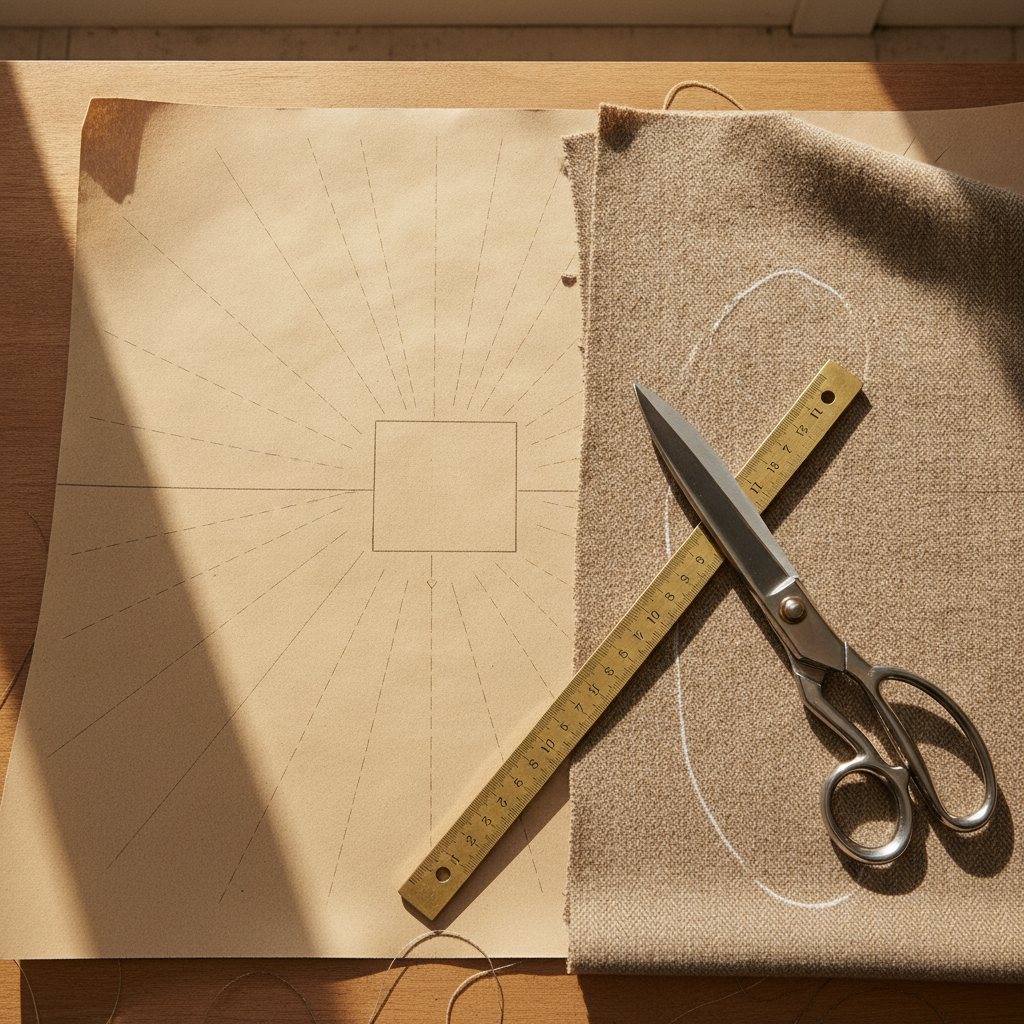
To identify these discrepancies before committing costly yardage, master pattern cutters embed a standardized Test Calibration Square—typically 50 mm × 50 mm or 2.0 inches × 2.0 inches—on the initial layout sheet. This box serves as the physical benchmark against which the hardware driver’s output must be rigorously interrogated.

The Atelier Calibration Formula: Mathematical Recovery
When your printed test square fails to match its target dimension, blindly guessing printer driver percentages wastes heavy paper stock, toner, and valuable studio hours. You can calculate the exact target output percentage using a direct proportional ratio.
The mathematical calibration formula is defined as:
Target Print Scale (%) = (Intended Test Dimension / Measured Physical Dimension) × Current Driver Scale (%)
Consider a practical studio scenario: Your pattern calls for a 50 mm test square, printed with the software set to 100%. Upon measuring the printed square with a calibrated brass tailor’s rule, you observe a physical width of 47.8 mm. Applying the formula:
- Intended Dimension: 50.0 mm
- Measured Dimension: 47.8 mm
- Current Driver Scale: 100%
- Calculation: (50.0 / 47.8) × 100 = 104.6025%
By entering 104.6% into your driver’s custom scale parameter, you compensate for the driver’s internal downscaling, forcing the vector engine to render the true physical footprint across the sheet.
Proportional Resizing vs. Structural Seam Integrity
Beyond calibrating distorted test boxes, the master patternmaker often needs to scale an entire foundational block up or down. This arises when converting a classic tote bag pattern to an oversized weekender, scaling down an embroidery motif for a bodice insert, or adapting an accessory block. However, proportional scaling comes with an atelier rule that must never be broken: You cannot uniformly scale pattern pieces that have integrated seam allowances.
When you scale a pattern piece up by 130%, a standard 1.5 cm (5/8 inch) seam allowance scales up to 1.95 cm. Conversely, scaling down to 75% shrinks the seam allowance to 1.125 cm. If an artisan sews the resulting pieces using standard seam guides, the internal garment volume will be fundamentally corrupted.
The Two-Step Decoupling Method:
- Strip the Allowance: Trace the net stitching line (the true seam line) by subtracting the standard seam allowance from the perimeter of the pattern piece.
- Apply the Scale Factor: Scale the pure geometry of the stitching line to your target dimensions using the proportional ratio.
- Re-draft Uniform Allowances: Manually draft a uniform, true seam allowance (such as 1.0 cm or 1.5 cm) around the newly scaled geometry using a parallel grading ruler.
🛠️ Interactive Atelier Tool: Pattern Scaling & Print Tiling Calculator
Skip manual math and cutting guesswork. Use our free interactive tool to instantly calculate your exact measurements, fabric yield, and project specifications:
Engineering the Multi-Page Tiling Grid
Full-scale couture gowns, tailored overcoats, and circular capes demand broad continuous sheets that far exceed the surface area of domestic A4 or US Letter paper. When preparing these master files, pattern drafters distribute the full-scale vector draft across a tiled matrix of individual sheets.
Grid Geometry and Page Formats
A multi-page tiling grid divides a comprehensive pattern layout into columns (horizontal axis) and rows (vertical axis). Standard formats include:
- ISO 216 A4: 210 mm × 297 mm (Standard internationally)
- ANSI Letter: 215.9 mm × 279.4 mm / 8.5 × 11.0 in (Standard in North America)
- ISO 216 A3: 297 mm × 420 mm (Atelier desktop standard)
- ISO 216 A0: 841 mm × 1189 mm (Commercial wide-format copyshop standard)
To assemble pages accurately, each sheet requires an overlap margin—typically 12 mm to 15 mm (or 0.5 inches)—printed with registration marks, corner targets, and alpha-numeric grid coordinates (e.g., Row B, Column 3). Without an exact overlap margin, attempting to abut raw cut paper edges creates systemic drift: a mere 0.5 mm gap per seam across an 8-column layout produces a 4 mm dimensional creep across the pattern piece, distorting the grainline alignment.
The Tiling Assembly Protocol: Step-by-Step
- Maintain a Datum Edge: Trim only the top and left margins of each printed sheet along the indicated cut lines. Leave the bottom and right margins intact to serve as receiving underlaps.
- Align Registration Crosshairs: Overlay the trimmed border directly atop the adjacent page’s registration crosshairs. Secure the intersection using a fine tailor’s awl to anchor the registration point before taping.
- Tension-Free Fastening: Apply low-tack repositionable tape or archival matte adhesive across the overlap. Avoid aggressive tape pulling, which induces localized paper buckling and distorts flat vector paths.
Fabric Grain Alignment & Cutting Protocol
Once your pattern foundation is calibrated and tiled to absolute precision, it must be translated to cloth. Digital scaling errors often mask subtle grain misalignments that compromise drape:
- Warp & Weft Tension: The straight grain of woven fabric runs parallel to the selvage along the warp threads, which possess minimal elasticity. If an uncalibrated pattern piece is rotated slightly to squeeze onto insufficient yardage, parts of the pattern will inadvertently fall on the true bias (a 45-degree angle to the warp and weft). This causes hemlines to ripple and seams to twist over time.
- Walk Your Seams Before Cutting: After assembling your calibrated paper pieces, always “walk” the joining seams. Stand the paper pattern pieces on edge and run the stitching lines against each other—front side seam to back side seam, sleeve cap to armscye. Ensure that notch pairs register within 1 millimeter of tolerance.
Completing Your Atelier Workflow
Meticulous pattern preparation distinguishes home sewing from true garment engineering. By controlling driver scale parameters, calculating proportional ratios, and maintaining rigid paper tiling protocols, you ensure that every line draped on the dress form manifests faithfully in the final cloth.
Once your calibrated pieces are cut and assembled, refine your project with our specialized studio calculators. When drafting balance closures and spacing plackets along your newly sized bodices, use our Buttonhole Calculator to ensure mathematically uniform button placement. Furthermore, if you are running a custom apparel business or bespoke alterations atelier, evaluate your studio labor and materials accurately using the Alteration Price Estimator to protect your craft margins.
Do you enjoy the content on Agenda Creativa?
Your contributions help me create new articles, share creative ideas, and keep this platform alive! If you like what I do and want to support my work, you can buy us a coffee.
Every cup of coffee means more than just a gesture – it's direct support for my passion to create inspiring and useful content. Thank you for being part of this journey!
☕ Buy me a coffee